1. PROBLEM IDENTIFICATION
Improperly designed transition or no transition at all between the curb and the street
at pedestrian crossings and in the vicinity of building entrances.
2. PLANNING PRINCIPLE
To overcome changes in level between the pavement and the road surface and also on the
pavement itself.
3. DESIGN CONSIDERATIONS
3.1 General
 Curb ramps are used wherever there is a
difference in level on pedestrian paths or cross paths. Curb ramps are used wherever there is a
difference in level on pedestrian paths or cross paths.
To avoid confusing sightless pedestrians,
curb ramps should be positioned out of the usual line of pedestrian flow. The unobstructed
width of the pathway should be not less than 0.90 m (see Pathways).
Curb ramps should be located away from places
where water accumulates.
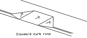
3.2 Types (a) Standard curb ramps: Cut back into the pavement with flared sides
providing transition in three directions (fig. 1).
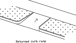
(b) Returned curb ramps: (1) Providing slope in one
direction. This could be a dangerous measure if the sides are not protected (fig. 2).
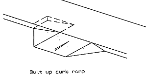
(c) Built-up curb ramps: (2) Usually with flared edges
(fig. 3).
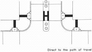
3.3 Application
At each quadrant of each street intersection
(fig. 4).
At each pedestrian crossing, on opposite
sides of the street (fig. 4).
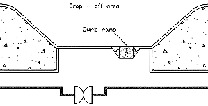
At drop-off zones, near building entrances
(fig. 5).
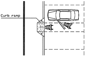
Between accessible parking areas and pathways
(fig. 6).
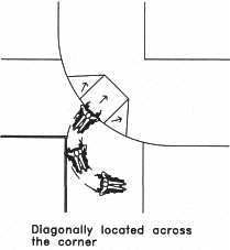
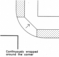
3.4 Curb ramps at intersections
At intersections, curb ramps can be installed
in any of the following ways:
(a) Directly in the path of travel (fig. 4).
(b) Diagonally across the corner (3) (fig. 7).
(c) Continuously wrapped around the corner (fig. 8).
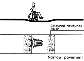
3.5 Narrow pavement
Where the construction of curb ramps would
affect the width of the travel route, the whole pavement should be lowered, at a maximum
slope of 1:12, to provide the necessary level transition (fig. 9).
For narrow pavements lowered at a corner, the
tactile tiling indicating the location of the pedestrian crossing could be constructed as
indicated in figure 10.
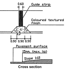
3.6 Width
The minimum width of a curb ramp should be
0.90 m, excluding the sloping sides. The recommended width is 1.20 m (4) (fig. 11).
3.7 Slope
The maximum slope of a curb ramp should be
1:12.
The maximum slope of flares should be 1:12.
Level transfer is recommended between the
curb ramp and the surface of a pathway. A lip not exceeding 15 mm can be used (fig. 11).
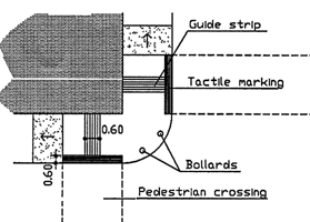
3.8 Guide strips
A guide strip painted in a contrasting colour
should be constructed to guide sightless and partially sighted pedestrians to the location
of the curb ramp (fig. 4). (see Pathway; Pedestrian
Crossings)
3.9 Surface and colour
Curb ramps, including flares, should have a
rough texture or ground pattern to make them detectable and slip-resistant.
The surface colour should be distinct and
should contrast with the surrounding surfaces to guide pedestrians with limited vision.
4. EXISTING CONSTRUCTIONS
The maximum allowable slope for a curb ramp
constructed along high pavements should not be more than 1:10. The maximum slope of the
flares should also be 1:10.
If existing curb ramps do not comply with the
above mentioned requirements, they should be modified.
For narrow pavements more than 0.15 m high,
where the construction of curb ramps would obstruct the free passage of pedestrians:
(a) The pavement can be lowered to the road level to obtain the required transition
between the pavement and the road surface (fig. 9) (fig.10).
(b) Built-up curb ramps can be constructed if they would not obstruct the required
width of the road (fig. 3).
Notes:
(1) Returned curb ramps are unaccepted measures in some countries.
(2) In some countries, such as Canada, built-up curb ramps are accepted only as
remedial measures to overcome existing barriers, but not on public streets or pathways.
(3) Corner curb ramps could be dangerous to wheelchair users if the pedestrian crossing
is not wide enough.
(4) The curb ramp construction at pedestrian crossings does not need to cover the whole
width of the crossing. |